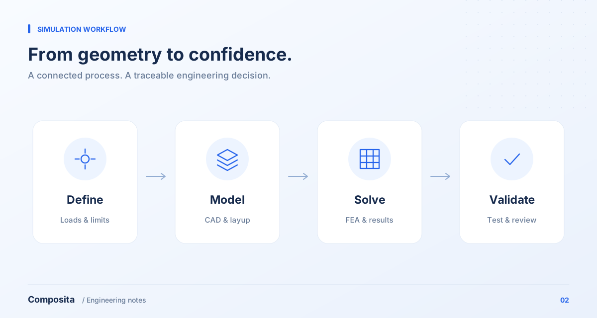
Define the decision first
State whether the analysis compares concepts, checks displacement, locates weak regions or supports a physical test. Each objective calls for different model detail and input quality. The report should answer that objective rather than merely present contour plots.
Create a load-case table with sources, directions, application locations, supports and acceptance metrics. Label unknown inputs as assumptions and plan sensitivity studies or measurements instead of silently assigning plausible numbers.
Make geometry, material and layup consistent
Check CAD units, thicknesses, connected surfaces and revision before choosing shells, solids or local refinements. Remove a small feature only after deciding whether it affects load paths, contact or local failure.
A composite model needs traceable material data, ply thicknesses, angles, stacking order and coverage. Use a simple coupon model to check units and directions before applying the same definitions to the component. Shell-model suitability depends on thickness, curvature and the objective; holes, joints or interlaminar-stress-dominated regions may need a local three-dimensional model.
Check behavior before interpreting failure
A completed solve is not evidence that the model is correct. Check force balance, deformation direction and contact behavior first. Define mesh-sensitivity metrics for displacement, reaction or a relevant region instead of relying on total element count.
State the failure criterion and the data it requires. Ply-level assessment can identify controlling plies and load cases, but a first-ply failure indicator is not automatically the ultimate failure load of the structure. Static results do not establish fatigue, impact or interlaminar performance that was not evaluated.
Deliver a reproducible assessment
Retain geometry revisions, material sources, mesh, layup, load cases, solver settings, findings and limitations. Tie proposed changes to findings, whether they involve section geometry, laminate design or interfaces.
Verification checks implementation of equations, code and numerical solution; validation assesses adequacy against the real system for the intended use. Mesh convergence is a numerical check, not proof of physical predictive accuracy. Plan a physical comparison. If calculated and measured displacement differ, review supports, actual thickness, materials and joint stiffness instead of merely tuning inputs to match a curve. The objective is a model that supports the next design decision.
References & further reading
Bring your engineering question.
Discuss material selection, structural design and analysis for your component with Composita.