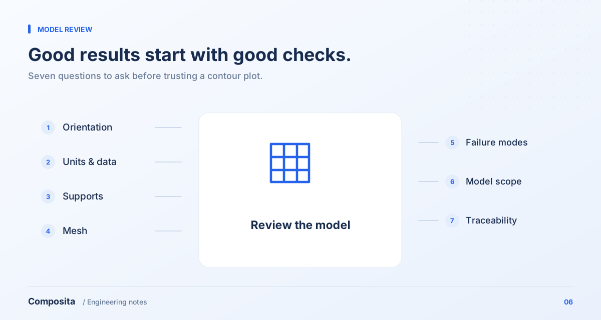
Mistakes 1–2: correct properties, incorrect application
First, ignoring material orientation. Correct elastic constants still describe the wrong component if local axes differ from the actual layup. Display the direction field and check curved transitions, mirrored parts and separate regions.
Second, mixing property levels or units. Fiber, lamina and laminate data are not interchangeable. Check stiffness, strength, thickness, density and units, and document the processing and test conditions associated with the data.
Mistakes 3–4: rigid supports and mesh-by-count
Third, fixing every mounting surface without considering real connection compliance, contact or slip. Compare plausible support assumptions. If the conclusion changes significantly, better interface information deserves priority.
Fourth, treating element count as proof of accuracy. Select a decision-relevant output and compare meshes against it. If stress keeps increasing near a point load or ideal sharp corner, investigate a possible singularity instead of refining until a preferred number appears.
Mistakes 5–6: one stress value and an overstated failure conclusion
Fifth, summarizing every composite failure risk with a single equivalent stress commonly used for metals. Choose an assessment appropriate to the material, failure mechanisms and available data, retaining controlling plies, directions and cases.
Sixth, interpreting a ply-level threshold as the ultimate load capacity of the complete assembly. Damage initiation, progression and final failure are different questions. Without a corresponding model or test, limit conclusions to the behavior actually assessed.
Mistake 7: inputs that cannot be reproduced
Keeping only plots and maxima makes it difficult to distinguish a design change from a setup change. Each report should trace back to geometry, layup, materials, supports and solver settings at a specific revision.
Ask what decision the model supports, which assumption could change the conclusion, and what the next measurement will validate. These questions provide a more useful quality review than checking only that the solver reported success.
References & further reading
Bring your engineering question.
Discuss material selection, structural design and analysis for your component with Composita.