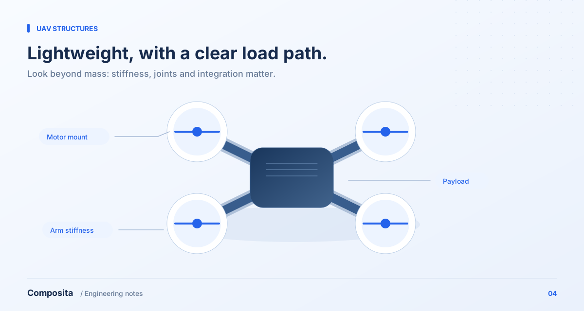
Map the load paths
Identify how loads from motors, batteries, payloads and landing gear enter the primary structure. Separate cruising, maneuvers, landing and handling rather than representing every condition with one vertical static load. Derive magnitudes from system requirements, measurements or documented estimates.
Draw a free-body diagram showing masses, thrust directions, reaction torque and supports. If inputs are uncertain, first identify which assumptions most strongly affect the decision and prioritize those measurements.
An arm needs more than bending stiffness
An arm can carry bending and torsion together, while its interfaces may be more flexible than the tube or plate. Compare motor-mount displacement and rotation alongside mass and stress. Increasing stiffness along one fiber direction does not necessarily resolve torsional behavior.
Evaluate vibration separately with modal or dynamic analysis, including motors, wiring, equipment masses and joints. A single unloaded natural frequency does not establish separation from every operating excitation.
Design assembly and maintenance in
Review bearing around holes, local compression and load transfer through metal inserts. Repeatedly dismantled connections need assembly procedures and inspection conditions, rather than depending entirely on operator experience.
Check access for cutting, drilling, layup and bonding. Include wiring routes, equipment mounting and battery replacement in the concept. A structure that is easy to make, inspect and replace can be more useful for iteration than one optimized only for theoretical minimum mass.
Compare the important predictions with a prototype
Plan measurements of arm-tip displacement, interface stiffness and assembly vibration. Record actual thickness, mass, material batch and assembly condition so differences from the model can be investigated.
This is a structural planning workflow, not a substitute for complete flight-system validation. Suitability for flight also depends on intended use, integration and applicable requirements.
References & further reading
Bring your engineering question.
Discuss material selection, structural design and analysis for your component with Composita.